Welcome: Jiangsu Hongjing Metal technology Co.,Ltd







yolanda@hongjingmetal.com +86-15358997067

Machine tool spindle bearings require precise preload installation to guarantee machining accuracy.
Proper mounting and precise preload of machine tool bearings directly guarantee spindle rigidity, rotational accuracy, low vibration, prolonged service life and consistent machining quality.
Insufficient preload causes runout, chatter and reduced stiffness; excessive preload leads to overheating, accelerated wear and premature failure. This procedure applies to angular contact ball bearings, tapered roller bearings commonly used in machine tool spindles.
Machine Tool Bearing Installation & Preload Adjustment Procedure
Follow our step-by-step guide for machine tool bearing installation and precision preload adjustment, covering mounting, measurement, run-in and safety to secure spindle rigidity, accuracy and long service life for milling, turning and grinding centers.
Pre-Work Preparation
1. Prepare correct bearing models, matched spindle/housing components, calibrated torque wrenches, dial indicators, micrometers, clean lint-free cloths, temperature-controlled heating tools (induction heater/oven), recommended lubricant/grease, protective gloves and goggles.
2. Inspect all parts: check bearing races, rolling elements, cages for damage, rust or contamination; verify spindle journals, housing bores, spacers, lock nuts/shims for dimensional accuracy, surface finish and burrs.
3. Clean all components thoroughly with approved solvent, dry completely; keep assembly area dust-free, temperature-stable to avoid thermal distortion during fitting.
4. Warm bearings uniformly (per manufacturer specs, do not exceed bearing temper temperature) for press-fit mounting onto the spindle; never use direct flame or hammer striking.
Step 1 Mount Bearings onto Spindle & Seat into Housing
1. Fit the inner ring of the heated bearing onto the spindle journal, push firmly until fully seated against the spindle shoulder; allow gradual cooling to form interference fit, ensure no axial gap or skewing.
2. Install paired bearings (DB/DF/DT arrangement as design requires), place intermediate spacers/ground shims between bearing sets, align bearing faces parallel and concentric.
3. Lower the spindle-bearing assembly into the machine tool housing carefully, avoid tilting or scraping outer rings; seat outer rings squarely in housing bores, install outer ring retaining components if specified.
4. Confirm free rotational movement by hand before applying axial clamping; no binding or rough rolling is allowed.
Step 2 Set Up Preload Mechanism & Measure Baseline
Two mainstream preload methods are covered: fixed position preload (shim/constant pressure) and constant pressure/spring preload
1. For shim-style fixed preload: loosely thread lock nuts/end caps, leave small axial play; mount dial indicators on spindle face/outer housing to capture axial displacement and radial runout.
2. For spring preload: install calibrated spring stacks behind outer ring housings, pre-compress springs to calculated free length per design load value before final fastening.
3. Rotate spindle slowly by hand, record initial endplay/runout readings as baseline.
Step 3 Perform Gradual Preload Adjustment
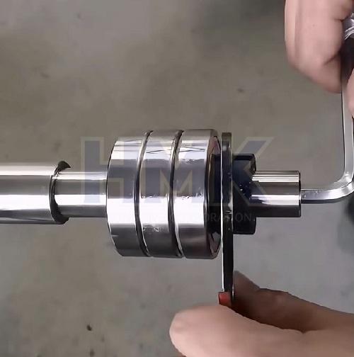
1. Tighten the lock nut/end cap incrementally (small angular turns, use torque wrench for controlled force) to reduce axial clearance step by step; pause after each small adjustment, rotate spindle full revolutions to let rolling elements seat evenly.
2. Monitor dial indicator: reduce clearance until measured residual play is eliminated, light drag is felt by hand rotation, and radial runout meets drawing tolerance (typically ≤0.002mm for precision spindles).
◦ If over-tightened (stiff rotation, sharp temperature rise on test spin): loosen slightly, check shim thickness, replace with thinner shims or release spring compression and restart.
◦ If too loose (noticeable axial endplay, wobble): add shim thickness or increase nut torque in tiny increments, repeat seating rotation and measurement.
3. For paired multi-bearing sets, adjust symmetrically on both ends to avoid spindle skew and uneven load distribution across bearing rows.
Step 4 Run-In & Verify Operational Parameters
1. Apply specified volume/grade of lubricant (grease or circulating oil mist); avoid over-greasing which traps heat.
2. Perform low-speed run-in (500–1000 RPM for 30–60 minutes), monitor bearing housing temperature with thermal sensors/infrared thermometer: stable operating temperature should stay below 60°C (140°F), no rapid spike.
3. Check radial/axial runout, spindle rigidity, noise (smooth hum only; grinding/screeching indicates misalignment or excess preload).
4. Recheck torque values and lock lock nuts with locking washers/thread locker to prevent loosening under cutting loads or thermal cycling.
Step 5 Final Assembly & Post-Installation Notes
1. Install seals, labyrinths and auxiliary components; confirm no lubricant leakage, coolant ingress pathways are blocked.
2. Document all data: bearing serial numbers, preload torque, runout measurements, temperature readings and timestamps for quality traceability.
3. Complete full-speed cutting trials across typical machining loads; re-inspect runout, vibration and temperature after 2–4 hours of operation, fine-tune if drift occurs.
4. Schedule periodic maintenance: recheck preload after heavy use, rebuild/replace bearings when persistent overheating, noise or runout drift appears.
CRITICAL WARNINGS
• Never strike bearings directly with hammers/punches; use press tools or thermal fitting only.
• Preload values must follow machine and bearing manufacturer specifications; avoid guesswork adjustment.
• Stop operation immediately if abnormal noise, rapid overheating or dimensional drift occurs to prevent spindle damage or workpiece scrapping.
• Wear personal protective equipment; maintain clean working conditions to exclude abrasive particles that shorten bearing life.
Contact us for more bearings technical guidance now
Contact: Yolanda
Phone: +86-15358997067
E-mail: yolanda@hongjingmetal.com
Add: No.88, Qianyao Road, Binhu District, Wuxi, China
LiveChatclose
 Send Email
 Skype
Skype WhatsApp