Welcome: Jiangsu Hongjing Metal technology Co.,Ltd







yolanda@hongjingmetal.com +86-15358997067
Taper bore bearings are widely used in heavy-load mechanical equipment.
The installation process needs to match adapter sleeves and lock nuts.
Put the bearing and sleeve in place evenly, then gradually tighten the lock nut to control bearing clearance accurately.
Avoid excessive locking which causes over-preload and bearing heating. After installation, check rotation flexibility and adjust preload properly.
Standard taper bearing installation ensures stable heavy-load operation.
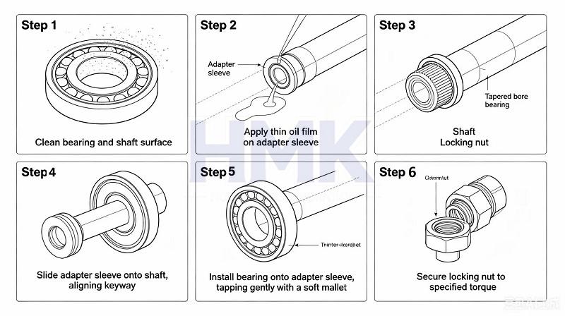
Step 1: Pre-installation Preparation
Clean the shaft surface, adapter sleeve inner/outer taper, bearing tapered bore, lock nut and lock washer thoroughly to eliminate rust, metal chips, grease and dirt. Wipe dry and apply a thin layer of clean lubricating oil on the sleeve outer taper and nut threads to avoid galling during tightening. Check all parts for scratches, deformation or thread damage before assembly.
Step 2: Fit Adapter Sleeve onto Shaft
Slide the adapter sleeve over the shaft with the threaded end facing outward, close to the pre-marked bearing installation position. Gently expand the sleeve’s split slot with a screwdriver if sliding resistance is high; never hammer the sleeve directly to prevent taper distortion. Position the sleeve against the shaft shoulder for axial limiting.
Step 3: Mount Bearing on the Adapter Sleeve
Align the large-diameter end of the bearing’s tapered bore with the sleeve’s big taper end, then slide the bearing onto the sleeve evenly. Rotate the bearing by hand to confirm smooth contact between two tapered surfaces without jamming. Do not install the lock washer at this stage, as axial pushing during clearance adjustment will damage the washer tab.
Step 4: Pre-tighten Lock Nut for Clearance Calibration
Screw the lock nut onto the sleeve thread with its chamfered side against the bearing inner ring. Tighten the nut lightly by hand first, then use a hook spanner or torque wrench to turn the nut incrementally. Push the bearing upward along the taper to reduce radial internal clearance until reaching the standard clearance reduction value specified by the bearing manufacturer.
Critical reminder: Overtightening drastically cuts internal clearance, generating extra heat and early fatigue failure; insufficient tightening leads to bearing sliding on the shaft under load.
Step 5: Lock with Lock Washer
After adjusting clearance to the standard range, back off the lock nut slightly to align the notches on the nut with the tab slot of the lock washer. Install the lock washer, then bend one washer tab into the nut notch to lock the nut rotation and prevent loosening during long-term operation.
Step 6: Final Inspection & Commissioning
1. Rotate the shaft manually to check smooth bearing rotation with no stuck points or abnormal friction noise.
2. Measure radial runout with a dial indicator to verify concentricity meets tolerance requirements.
3. Double-check all contact surfaces and locking components for secure assembly.
4. Conduct no-load trial running for 10–15 minutes; monitor bearing temperature. Stop immediately if abnormal overheating or vibration occurs for rechecking.
Key Installation Notes
1. Avoid direct hammer striking on bearing rings, sleeves or nuts during the whole process; use mounting sleeves for uniform force transmission.
2. Follow the manufacturer’s recommended torque or clearance reduction data instead of random force control.
3. For high-speed and heavy-load working conditions, hydraulic nuts are suggested for more uniform axial pushing.
4. Regular re-tightening inspection is required after equipment initial operation to compensate for micro creep of the tapered fitting surface.
Correct adapter sleeve mounting maximizes bearing service life and ensures stable running performance of rotating machinery. Our engineering team provides customized bearing matching and on-site installation guidance for global industrial clients.
GET MORE BEARING SOLUTIONS NOW
Contact: Yolanda
Phone: +86-15358997067
E-mail: yolanda@hongjingmetal.com
Add: No.88, Qianyao Road, Binhu District, Wuxi, China
LiveChatclose
 Send Email
 Skype
Skype WhatsApp